The working principle of the high voltage transformer
The working principle of the high voltage transformer
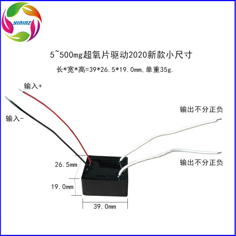
The working principle of high voltage transformer is actually a device that converts low voltage into high voltage, including AC-AC, AC-DC, DC-AC, DC-DC, some people call a simple step-up transformer component also called high voltage package, This is not appropriate.
The working principle of the high voltage package
The conventional high-voltage package circuit consists of transistors VT1, VT2 and inductors L1-13, pulse transformer T, current limiting resistor R1, charging capacitor C3, two-way trigger diode D5, etc. to form a push-pull oscillation circuit; filter inductor coil L0, rectifier diode VD1 It forms a half-wave rectifier filter circuit with filter capacitors C1 and C2. Connect the AC power supply, the AC 220V voltage is filtered by LO, and after VD1 rectification, a voltage of about ten 280V is generated at both ends of C1, which is supplied to the push-pull oscillation circuit. At the moment of startup, VT1 is turned on. Due to the charging effect of C3, the two-way trigger diode VD5 is cut off. When the charging voltage across C3 rises to 32V, VD5 is triggered and turned on, making VT2 turn on. During the VT2 conduction period, C3 gradually discharges, and VT2 is turned off. After VT1 is turned on, under the action of the pulse transformer T, a positive feedback voltage is generated on L1 and L2. This voltage is added to the bases of VT1 and VT2 respectively, so that VT1 and VT2 are turned on and off alternately (that is, when VT1 is turned on, VT2 is off; when VT2 is on, VTl is off), the push-pull oscillation circuit oscillates. After the push-pull oscillation circuit works, pulse high voltage is generated on the secondary winding L6 of the pulse transformer T; when the DC power supply is turned on, the corresponding DC voltage, such as 5V, is filtered by LO, and after VD1 rectification, ten pulses are generated at both ends of C1. The voltage of about 5.2V is supplied to the push-pull oscillation circuit. At the moment of startup, VT1 is turned on. Due to the charging effect of C3, the two-way trigger diode VD5 is cut off. When the charging voltage across C3 rises to 2V, VD5 is triggered and turned on, making VT2 turn on. During the VT2 conduction period, C3 gradually discharges, and VT2 is turned off. After VT1 is turned on, under the action of the pulse transformer T, a positive feedback voltage is generated on L1 and L2. This voltage is added to the bases of VT1 and VT2 respectively, so that VT1 and VT2 are turned on and off alternately (that is, when VT1 is turned on, VT2 is off; when VT2 is on, VTl is off), the push-pull oscillation circuit oscillates. After the push-pull oscillation circuit works, pulse high voltage is generated on the secondary winding L6 of the pulse transformer T.
Component selection VTl, VT2 select 2SC2653 or BU406 silicon NPN high back pressure triode. The current amplification factor β>100 is required. VDl-VD4, VD6 select 1 N4007 type rectifier diode; VD5 selects DB3 type bidirectional trigger diode. R1 to R6 all use RJ-1/8W metal film resistors. L0 is a 50UH plug-in inductance coil. You can use Φ0.45mm enameled wire to wind 50 turns on the skeleton; the choice of pulse transformer is very important, and it must be made by a regular manufacturer with a voltage resistance of more than 10,000V, otherwise the service life will be greatly Shorten; All electronic components are installed on a self-made printed circuit board, and the external whole is potted with epoxy resin. The withstand voltage after potting of the whole needs to be more than 2 times the actual output high voltage, as long as the components are good and the wiring It is correct, and it can work normally after power on.


